Options - Layout Pictures
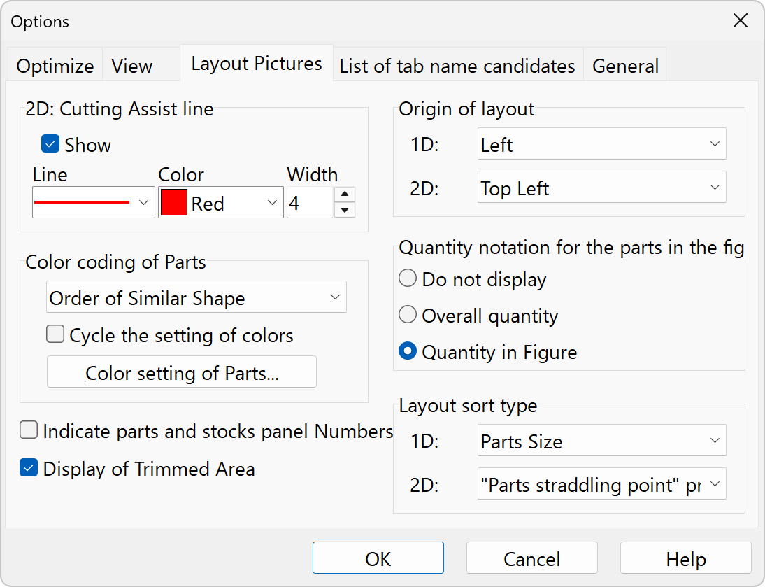
Menu: [Tool]-[Options]-[Layout pictures]
Cutting aid lines: 2D
When displayed, it is easy to see where the board is to be cut from. It may not be displayed for simple patterns.
Origin of Layout: 1D, 2D
Set origin of the layout. The orientation of the figure changes with the same content.
Color coding of Parts
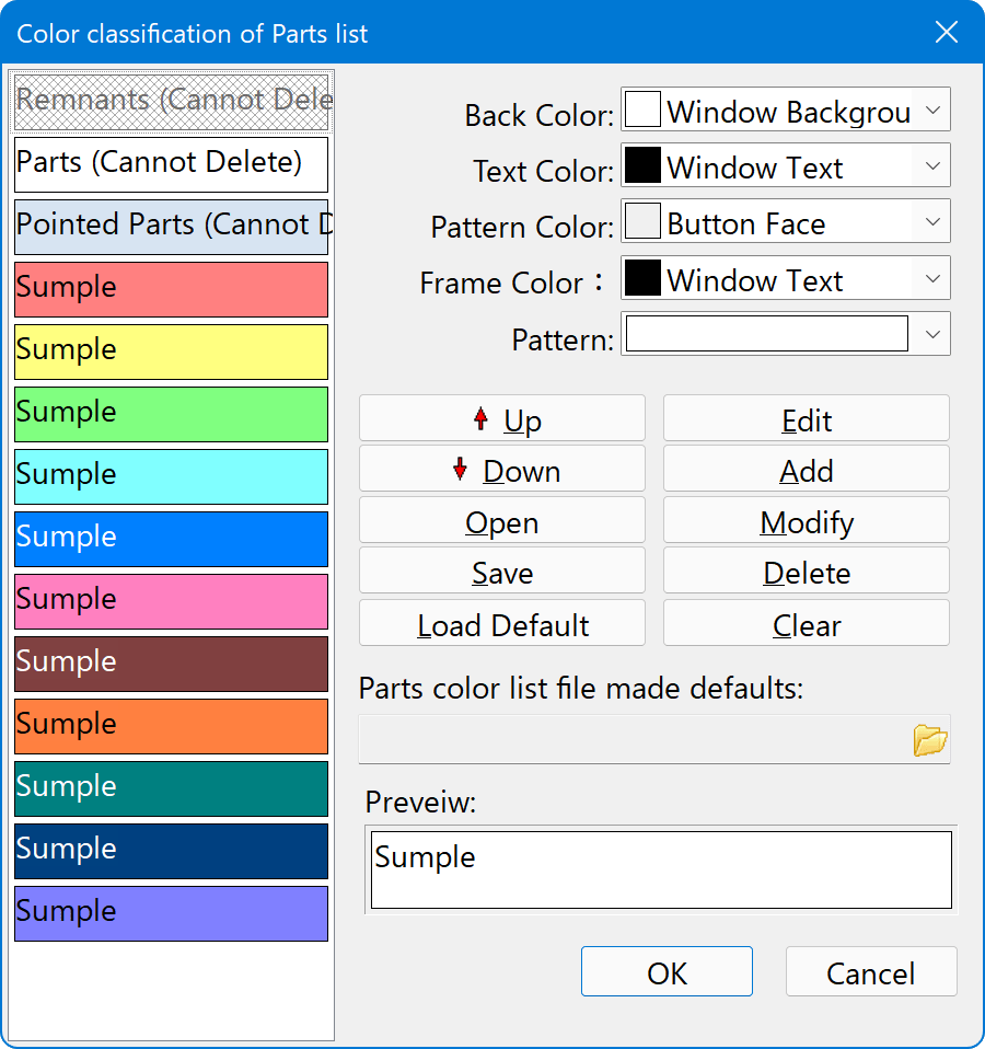
The top three colors on the list are standard color settings and cannot be deleted.
How to change colors
- Select the color list on the left
- Change colors, etc. in the upper right list box
- Press the [Change] button
To change the default values when you start the program
- Save the color settings to a file with the Save button
- Select the parts panel file you want to use as the initial value.
If you leave this field blank, the settings will return to the settings at the time of application installation.
Display of Parts panel and Stocks panel numbers
Displays the numbers that are automatically assigned to Parts panel and Stocks panel. If a comment is too long to fit in the Parts panel, the number is not used to distinguish the parts panel.
Show trimmed areas
Unchecking this checkbox will omit trimming, if any.
Parts panel quantities in drawings
When displaying the quantity of parts panels in a drawing, specify whether the quantity is for the entire drawing or just the parts in the drawing.
The upper right corner of the drawing will indicate how many copies of the same pattern there are in the drawing. If you select "Quantity in Figure," the actual cutting operation will require the quantity multiplied by the number of pieces.
Layout sort type
1D
- Size of leftover material
Arrange the drawings in order of the highest yield. - Parts Size
Arrange the larger part panels in weighted order. The idea is that cutting from the larger part panels will often allow you to reuse the smaller ones if you make a mistake, so cutting from the top in this order will result in less waste. - Count of per Layout
Arrange them in order of the number of diagrams with the same cutting pattern.
2D
- Stock Size - "Parts panel straddling point" priority
Arrange the drawings in order of the largest original plate size. For drawings of the same size, arrange them in order of the number of "Parts panel straddling points" priority. - "Parts panel straddling point" priority
Arrange the parts in order of the number of "Parts panel straddling points." If there are multiple sizes of original plate, drawings of different sizes will be inserted in between.