.recx file format
A .recx file is Cutting Planner\'s proprietary file format, which is a .xml worksheet file that has been zipped and given a .recx extension. One .xml file is equivalent to one worksheet, so you do not need to be aware of the fact that it is a .zip file. You do not need to be aware of the fact that the file is a zip file, nor do you need to install separate compression and decompression software.
Generally, only the creator of a binary file understands the specifications of the binary format. Therefore, it may be difficult to reuse the data due to changes in the times. This software is a minor proprietary standard, and I think that leaving a large amount of data in this format will inevitably leave some concerns.
Therefore, we have changed to xml format. xml is flexible enough to accommodate future specification changes and extensions. By publishing the specifications, third parties can develop software to use the output tree plans in other applications. The advantages are as follows.
If you put extra files in the .recx, it may not work properly.
Multiple .xmls can be combined into a zip to support multiple sheets. The tab order is the order of the file list inside the zip. This allows you to create a multiple-sheet .recx file even on the command line by using the zip file creation tool.
目次
- Data structure
- Example of 2D code
- Option
- SourceBoardList: Stock Sheet List
- StockBoardList: Priority Stock Sheet List
- PartsBoardList: Parts List
- SourceBoardData: Aggregated Stock Sheet Data
- PartsBoardData: Aggregated Parts Data
- Memo
- Parts Color Settings List
- Cutting Plan List
- PanelSaw: Data for a single cutting plan
- CuttingCoordinateList: 2D only, Coordinate list for parts and offcuts
As an example, here is an xml of the following data.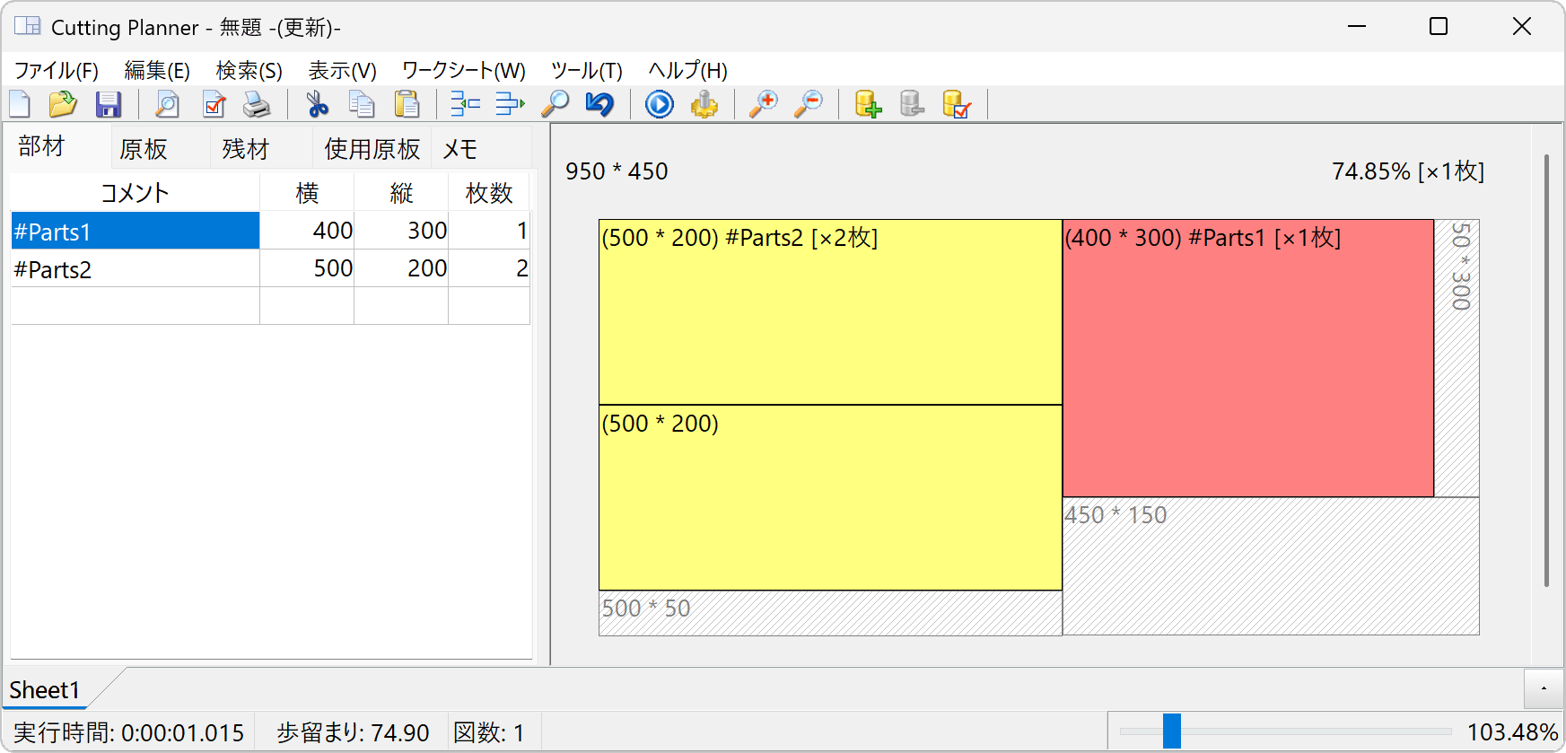
Data structure
If you are only performing data input, providing just <PartsBoardList> and <SourceBoardList> is sufficient.
─RectPacker
├─Memo
│ └─Line (Text per line)
├─Option
├─PanelSawList (1D or 2D cutting plan list)
│ └─PanelSaw (Cutting plan)
│ ├──CuttingCoordinateList (2D: Coordinate list for parts/offcuts)
│ └─LineData (1D) or BoardNode (2D: Cutting plan)
├─ProcessNumberPriorityPanelSawList (1D process-count priority) or RemnantsLengthPriorityPanelSawList (1D offcut-length priority)
│ └─PanelSaw (Cutting plan)
│ └─LineData
├─PartsBoardList (Parts list)
├─PartsColorList (Color settings list for parts)
├─SourceBoardList (Stock sheet list)
├─StockBoardList (Priority material list)
├─SourceBoardData (Aggregated data for stock sheets)
├─PartsBoardData (Aggregated data for parts)
└─PrintSetUp (Print page settings)
Regarding Part Numbers and Stock Sheet Numbers
Parts and stock sheets are sorted by area, and numbers starting from 0 are assigned starting from the largest. If the areas are equal, the one with the longer horizontal dimension is numbered first; if those are also equal, the rotatable one is numbered first. However, the value displayed on the application screen is this number +1. This change was made for users who find it counterintuitive for numbering to start at zero. Since changing this internally would cause issues such as compatibility with legacy files, the numbering in this XML file begins from zero.
Regarding the BoardNode Tag: 2D Cutting Plan Data Structure
The <BoardNode> tag is visually too complex for humans to understand, so we have added the <CuttingCoordinateList> tag, which extracts only the coordinates. We recommend using this tag for standard purposes.
Inputting contradictory values may cause Cutting Planner to malfunction. Please use only the values that have been output by the software.
Example of 2D code
<?xml version="1.0" encoding="UTF-8"?>
<RectPacker FileTypeVersion="3.7" ExeFileVersion="15.40" WindowsVersion="10.0.26200" UserID="XXXXXXXXX">
<FormatSettings DecimalSeparator="." ThousandSeparator=","/>
FormatSettings DecimalSeparator="." ThousandSeparator=","
The decimal separator and thousands separator settings of the PC that saved this file. They will be converted if opened on a PC with different regional settings.
<Option SheetName1="Sheet1_#2" SheetName2="" Material="Sheet1_#2" Thickness="" SameSizePartsMerge="False" TabColor="clBtnFace" Problem="2D" LengthFormat="ftDecimals" Precision="1" Decimals="0" Rotate="0" SmallSourcePriorityPoint="1" PartsColorListType="1" KerfSize="3" ConvergenceJudgmentTime="10" TopTrimSize="" BottomTrimSize="" LeftTrimSize="" RightTrimSize="" Objective="MaximizeYield" FigureSortOrder="sotSourceSize" DescriptionCount="1" DescriptionTitle="" MethodOfLeavingRemnants="lrArea" MaxCutLength="" ComparisonOrder="rtYield,rtDrawingsQty,rtContiPartsArrange,rtPartsStraddlingPoint,rtRotationalRrocesses,rtMaxRemainingSize"/>
Option
- SheetName1
or Material: Sheet name 1 - SheetName2
or Thickness: Sheet name 2 - SameSizePartsMerge="true": Merge parts of the same size
- TabColor="": Tab color (clBtnFace is default)
- Problem="2D": Optimization problem type (1D or 2D)
- LengthFormat="ftDecimal": Length format
- ftDecimal: Decimals
- ftFeetDecimalInches: Feet and decimal inches
- ftFactionalInches: Fractional inches
- ftFeetFractionalInches: Feet and fractional inches
- Precision="1": Precision / Minimum unit
- If LengthFormat = "ftDecimal": 1, 0.1, 0.01
- If LengthFormat = "ftFeetDecimalInches": 0.1, 0.01, 0.001
- If "ftFactionalInches" or "ftFeetFractionalInches": 1/8", 1/16", 1/32", 1/64", 1/128"
Decimals="0": Number of decimal places(Precision takes priority; kept for legacy compatibility) - Rotate="0": All parts rotatable=0, All parts non-rotatable=1, Individual settings=2
- SmallSourcePriorityPoint="5": Priority level for using smaller stock sheets first
SearchLevel="4": Layout search level (Legacy)HighRatio="1": Legacy compatibility (0 for SearchLevel=1, 1 for SearchLevel>1). Integrated into ConvergenceJudgmentTime in Ver13.- PartsColorListType="1": Part coloring
- None=0
- Similar shapes=1
- By size (Large to Small)=2
- By size (Small to Large)=3
- KerfSize="3": Kerf width (Saw blade thickness)
- MaxCutLength="": Maximum possible cut length (2D)
- ConvergenceJudgmentTime="15": Search level (Convergence judgment time)
- Top/Bottom/Left/RightTrimSize="0": Trim sizes
RotationalProcessesPriority="1": Priority for number of rotational processes (2D)- PlacementPriority1D: For 1D only
- "lrProcesses": Process-count priority
- "lrRemnants": Offcut-length priority
- DescriptionCount="1": Number of columns in the comment section
<SourceBoardList>
<Board Comment=" " Width="950" Height="450" Count=" " Cost="1000"/>
<Board Comment=" " Width=" " Height=" " Count=" " Cost=" "/>
SourceBoardList: Stock Sheet List
Recorded exactly as entered in the app (except blank lines are removed). Invalid values are ignored during execution. For 1D, "Height" is omitted.
- Comment: Comment
- Width: Horizontal size
- Height: Vertical size
- Count: Number of sheets
- Cost: Unit price
</SourceBoardList>
<StockBoardList>
<Board Comment=" " Width=" " Height=" " Count=" " Cost=" "/>
</StockBoardList>
StockBoardList: Priority Stock Sheet List
Recorded exactly as entered in the app (except blank lines are removed). Invalid values are ignored during execution. For 1D, "Height" is omitted.
- Comment: Comment
- Width: Horizontal size
- Height: Vertical size
- Count: Number of sheets
- Cost: Unit price
<PartsBoardList>
<Board Comment="#Parts1" Width="400" Count="1" Height="300"/>
<Board Comment="#Parts2" Width="500" Count="2" Height="200"/>
PartsBoardList: Parts List
Recorded exactly as entered in the app (except blank lines are removed). Invalid values are ignored during execution.
- Comment: Comment
- Width: Horizontal size
- Height: Vertical size
- Count: Quantity
- CanRotate: Rotatable=1, Non-rotatable=0 (Used for individual settings; ignored otherwise)
</PartsBoardList>
<SourceBoardData>
<Board Index="0" Count="-1" Cost="1000" UsedNumber="1" Priority="0" Comment="" Width="950" Height="450"/>
</SourceBoardData>
SourceBoardData: Aggregated Stock Sheet Data
Duplicates and invalid values are removed; sorted by area and index.
- Index: Stock sheet number
- Comment: Comment
- Width: Horizontal size
- Height: Vertical size
- Count: Quantity (-1 indicates unlimited)
- Cost: Unit price
- UsedNumber: Number of sheets used
- Priority: 1 if it is a priority material
<PartsBoardData>
<Board Index="0" Width="400" Count="1" Cost="280.701754385965" Comment="#Parts1" Height="300" CanRotate="true" CanNotBeArrangedNumber="0"/>
</PartsBoardData>
PartsBoardData: Aggregated Parts Data
Duplicates and invalid values are removed; sorted by area and index.
- Index: Part number
- Comment: Comment
- Width: Horizontal size
- Height: Vertical size
- Count: Quantity
- CanRotate: Whether rotation is allowed (ignored unless individual settings are used)
- Cost: Unit price per sheet
- CanNotBeArrangedNumber: Number of parts that could not be placed
<Memo>
<Line>Sample line 1</Line>
<Line>Sample line 2</Line>
</Memo>
Memo
Recorded line by line.
Parts Color Settings List
Back=Background color, BrushColor=Pattern color, FontColor=Text color, PenColor=Border color, Style=Pattern type.
(Search for "Delphi VCL Color" or "Vcl.Graphics.TBrushStyle" for available values.)
<PanelSawList ExecutionTime="203">
Cutting Plan List
ExecutionTime = Execution time in milliseconds.
RotationsNumber = Total number of rotation processes (2D).
For 1D:
Contains the layout data set in the "PlacementPriority1D" option.
If "Process-count priority (lrProcesses)" and "Offcut-length priority (lrRemnants)" yield different results, the alternative result is listed using the following tags.
PanelSaw: Data for a single cutting plan
1D
Count: Number of identical layouts.
SourceIndex: Stock sheet number.
2D
Count: Number of identical layouts.
SourceIndex: Stock sheet number.
PartitionID: If the PanelSaw is part of a split layout, it is numbered from 1. 0 means not split.
PartitionIndex: Numbered from 0 within the same PartitionID.
PartitionCount: Indicates the number of sheets split within the same PartitionID.
LayoutNumber: Unique ID assigned as a drawing number.
RotationsNumber: Number of rotation processes for this plan.
CuttingCoordinateList: 2D only, Coordinate list for parts and offcuts
Because the BoardNode tag below is difficult for humans to read, this list provides the Top-Left and Bottom-Right coordinates for parts and offcuts in the layout.
- cgPartsSide: Part
- cgPartsLength: Part rotated 90 degrees
- cgSpace: Offcut (Remnant)