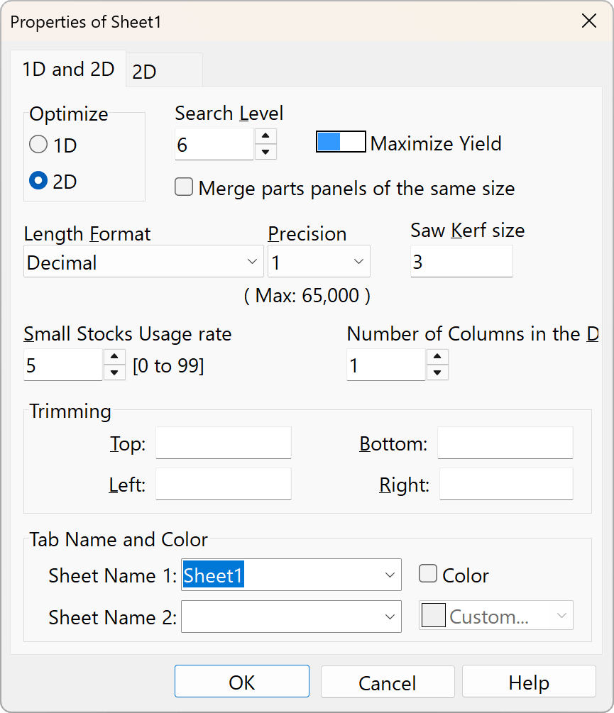
Sheet Properties - 1D and 2D
[Worksheet] > [Add Sheet] or [Worksheet] > [Change Sheet Properties]
What is a sheet?
This feature is similar to the ability to work with multiple worksheets in spreadsheet software. It allows you to manage multiple types of materials and board thicknesses all within a single file.
A .recx file is created by saving the data from a single sheet as an .xml file, then zipping multiple sheets together and changing the file extension.
You can add worksheets from other files by selecting [Worksheet] > [Insert from File].
Configure options such as layout calculations in the sheet properties.
1D and 2D Optimization options, etc.
With a few exceptions, you can apply these options to all sheets via the right-click menu.
Optimization Problem
You cannot switch between 1D and 2D modes while data is entered. To do so, either delete all parts panel and source panel lists, or use the “Add/Remove Sheets” option in the [Worksheet] menu.
Sheet Name
You can register frequently used names in the “List of Tab name candidates” list in the “Options” window to use when naming sheets.
For example, you can create names based on combinations of two types of information, such as material name and board thickness.
Search Level
Set the balance between search time and optimization. The more time you spend searching, the greater the chance of finding a better solution. However, for most problems, the search will never end. Therefore, the search will terminate when it has found at least the number of configuration patterns specified here, and when no better solution than the current best solution has been found for the specified number of seconds.
Since the search is terminated based on time, results may vary depending on the PC’s performance, even for the same problem. In other words, the slower the CPU, the longer the time should be set. Since the system supports multi-core processors, PCs with more cores have an advantage. Additionally, even for the same problem and the same PC, results may differ depending on timing because searches are performed separately and in parallel. For problems with few possible combinations, the search may finish faster than this time limit. Setting the value to “0” produces results as quickly as possible. In two dimensions, setting the value to “0” will produce a sufficient yield in most cases; however, allowing more time will generate Layout Pictures that reduce the number of cutting operations while maintaining the same yield.
Maximize Yield / Minimization Cost
Specify the optimization objective.
If you have selected [Minimize Cost], please enter all unit prices in the Source panel.
If you do not enter accurate unit prices, you will not get the intended results.
If you select [Maximize Yield] (default), setting the source panel unit price will not affect the placement calculation.
In most cases—such as when there is only one type of source panel or when there is little difference in the unit price per area—selecting “Maximize Yield” is sufficient.
Items in the “First usage Stocks list” are consumed first, regardless of this setting, starting with those with the smallest area.
Merge parts panels of the same size
Treating part panels of the same size as identical improves calculation efficiency.
If this box is checked, the description fields will be concatenated using “|”. Uncheck this box if you want to keep the drawings separate even for part panels of the same size.
Length Format
- Decimal
Example:1830.2
Please use [decimal] as usual.
Feel free to use any units of measurement, such as millimeters, centimeters, or inches. - Feet and decimal inches
Example:10' 3.5" - Fractional inchs
Example:15-1/2" - Feet and Fractional inches
Example:3' 5-1/8"
The denominator for fractional inches corresponds to 2, 4, 8, 16, 32, 64, and 128 within the specified accuracy range. When entering inches, the symbol on the far right may be omitted. The unit symbols for feet and inches are [ft], [′], and [\'], while those for inches are [in], [“], and [”].
Precision
Set the minimum unit. For decimal numbers, specify the number of decimal places. Since this app is designed to perform calculations only with integers internally, this setting determines the range of valid values. Length settings such as Saw Kerf Size, Trimming Size, and Cut Table Length also follow this setting. If a value falls outside the valid range, the text color of the data will turn red by default, and the data will be ignored during layout calculations. When the calculation is executed, the setting will be automatically adjusted to match the value with the highest number of decimal places.
Changing the length format or precision will not convert data that has already been entered.
Saw Kerf size
Specify the cutting width of the saw. Set this to 0 for shearing.
Enter a value in the format specified by “Length Format” and “Precision.” To enter values in 0.1 increments, set the precision to 0.1.
Small Stocks Usage rate
Applies only when the [Maximize Yield] setting is enabled. Enter a value between 0 and 99; the higher the value, the higher the priority given to smaller Source panels. Since smaller Source panels are typically cheaper per unit and easier to handle, adjust this setting while reviewing the actual layout calculation results.
“Priority Stocks” are consumed first, regardless of this setting, starting with the smallest Source panels. Use this option when you want to clear out scrap inventory, for example.
Number of columns in the description section
You can increase the number of description columns to a maximum of three.
Please note that if you are importing or exporting data via CSV files, changing the number of columns may cause compatibility issues.
Trimming
Specify the area at the edge of the source panel where parts cannot be placed. Enter a value in the format based on the “Length Format” and “Precision” settings. To enter values in 0.1 increments, set the precision to 0.1.
You can set the type and color of the trim lines in [Options] > [Layout Pictures].
Tab Name and Color
You can register frequently used names in the “List of Tab name candidates” list in the [Options] window to use them for sheet names.
For example, you can create names by combining two types of information, such as material name and specifications, or material type and sheet thickness.